Help creating organic looking "blobs"

Hello there!

I recently started getting to grips with Processing - and I love it so far!

I want to be able to randomly create organic looking “blob” shapes - like these (which were drawn in Illustrator): Blobs

What I have now is based on this example: Noisy Circle

The example uses perlin noise on vertices forming a circle. I’ve changed it to make curveVertex instead to make the shape softer. It works sort of okay, but it still looks a bit “edgy” and not as smooth.

I tried experimenting with bezierVertex, but it takes 6 parameters - and I’m afraid I don’t have the brain power to figure out if I can use bezierVertex to generate a random, organic shape…

This is what I have now (including my own Danish comments):

float resolution = 13;  // Antal vertices i blob (virker bedst fra 13+)
float rad = 300;  // Radius på blob
float x;  // X-koordinat på vertex
float y;  // Y-koordinat på vertex
float round = random(0, 100); // Rundhed - jo større tal, jo mere aflang

float nVal; // Noise: Værdi
float nInt = 10; // Noise: Intensitet
float nAmp = 0.4; // Noise: Udsving
float nSeed = random(0, 1000); // Noise: Unik værdi

float t = 0; // Tid passeret
float tChange = 0.01; // Hvor hurtigt tiden går

void setup() {
  size(1000, 1000);
}

void draw() {
  background(255);
  pushMatrix();  // Isolér placering til hver enkelt blob (push)
  translate(width/2, height/2);  // Placering af blob (samt bevægelse på Y-aksen)
  noiseDetail(3, 0);  // Noiseværdier
  noStroke();  // Ingen streg
  fill(100);  // Fyldfarve

  /* Oprettelse af blobform */

  beginShape();  // Begynd form
  for (float a=-1; a <= TWO_PI; a += TWO_PI/resolution) {  // Skab punkter rundt i hel cirkel (TWO_PI) og fordel dem ud fra resolution

    nVal = map(noise(cos(a)*nInt+nSeed, sin(a)*nInt+nSeed, t), 0.0, 1.0, nAmp, 1.0);  // Map noiseværdi for at matche udsvinget

    x = cos(a)*(rad+round) *nVal;  // Punktets X-koordinat (radius+rundhed)
    y = sin(a)*rad *nVal;  // Punktets Y-koordinat

    curveVertex(x, y);  // Opret curveVertex punkt ud fra koordinater
  }
  endShape(CLOSE);  // Afslut form

  popMatrix();  // Isolér placering til hver enkelt blob (pop)

  t += tChange;
}

How do I make the shapes more fluid, smooth and rounded?

All comments are highly appreciated. :slight_smile:

1 Like

Hi @Hetoft,

Do you want your final output to be a static image or an animation ?

Hi solub,

Thanks for replying. Animated is ultimately the end goal, but static would be fine as a start.

There are different ways to achieve that organic look you’re looking for but I’m afraid that noising a circle isn’t the best option.

The edges on your example sketch do look “smooth” (no need to use bezierVertex()) but the reason you’re not satisfied with it is because the height around the center is lacking contrast / variation. Based on the picture you provided I’d say that “splatter effect” is what you’re actually after.

Still, we can try to change your sketch a bit. Modifying the noise function and do some scaling will somewhat improve both the motion and the shape of the circle:
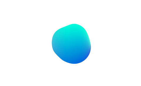
Noicy%20circle

see motion here

(please note that I’m using Python mode but it should be really easy to port it to Java)

n_points, radius = 200, 300
angle = radians(360) / n_points
factor = .2

def setup():
    size(800, 600, P2D)
    noStroke()
    smooth(8)

    beginShape() #Avoid calling beginShape() at each iteration 
        
def draw():
    background(255)

    translate(width>>1, height>>1)
    
    for e in range(n_points+1):
        x = cos(angle * e) * radius
        y = sin(angle * e) * radius 
        p = PVector(x, y).normalize()
        n = map(noise(p.x * factor + frameCount*.01, p.y * factor + frameCount*.01), 0, 1, 10, 200)
        p.mult(n)
        fill(100 - e / 10 - abs(p.y), (90 + e) - (p.y/4), 220)
        vertex(p.x, p.y)
    endShape(CLOSE)

In order to get a more blob looking shape I would suggest different approaches:

1/ Iso-surface (Metaballs)

Daniel Shiffman did a coding challenge on Metaballs a while ago. You can implement your own distance field based on his code or you can chose to use a library instead. I’ve found Computational Geometry to be one of the easiest to use for this purpose.

(see the bunddled examples for Java sketches)

add_library('ComputationalGeometry')

def setup():
    size(800, 500, P3D)
    rectMode(CENTER)
    background(255)
    noStroke()
    smooth(8)
    
    iso1 = IsoContour(this, PVector(), PVector(width, height), 200, 125) #last 2 int are the number of columns and rows. The higher, the better the resolution
    iso2 = IsoContour(this, PVector(), PVector(width, height), 200, 125)
    thresh = .0004 #the lower, the bigger the blobs
    
    for i in range(20):
        p1 = PVector(random(50, width - 50), random(height), 0)
        p2 = PVector(random(50, width - 50), random(height), 0)
        iso1.addPoint(p1)
        if i> 5: iso2.addPoint(p2)
        
    
    fill('#002d6b')
    rect(width>>1, height>>1, width - 120, height)
    
    fill('#e01a2c')
    iso1.plot(thresh)
    fill('#ffc20e')
    iso2.plot(thresh)

2 majors drawbacks:

  • because of the need to compute distances from each point on the grid to the ball (and this, for each ball), the algorithm is computationally expensive. Hence the difficulty to make an animation, unless you decide to implement it in a shader.
  • because it is making use of the whole array of pixels (loadPixels / updatePixels in its naive implementation) it is not possible to select the color of a specific ball.

2/ “Gooey Effect”

Visually similar to metaballs, it is a technique coming from the Web design community that consists in applying SVG filters (gaussian blur + high contrast in the alpha channel) on moving ellipses in order to get blob-like motions.

Example of a gooey effect implemented in three.js by Misaki Nakano. See it live here

Although the melting effect doesn’t look as good as in the original Javascript version, noahbuddy from the forum did a fantastic job trying to port that technique in Processing with a shader.

(See original Java version here)

def setup():
    global buf, balls, contrast, blurry
    size(1240, 720, OPENGL)
    rectMode(CENTER)
    noStroke()
    smooth(8)

    buf = createGraphics(width, height, P2D)
    contrast = loadShader("colFrag.glsl")
    blurry = loadShader("blurFrag.glsl")
    
    blurry.set("sigma", 10.5)
    blurry.set("blurSize", 30)
    
    balls = [Ball() for e in range(40)]

def draw():
    background(255)
    
    fill('#002d6b')
    rect(width>>1, height>>1, width - 120, height)
    
    buf.beginDraw()
    buf.background(190, 0)
    buf.noStroke()
    for b in balls:
        b.update()
        b.render()
        
    blurry.set("horizontalPass", 1)
    buf.filter(blurry)
    blurry.set("horizontalPass", 0)
    buf.filter(blurry)
    buf.endDraw()
    
    shader(contrast)
    image(buf, 0, 0, width, height)
    
             
class Ball(object):
    def __init__(self):
        self.loc = PVector(random(width), random(height), 0)
        self.vel = PVector.random2D()
        self.radius = random(60, 140)
        self.c = [[224,26,44], [255,194,14]]
        self.r = int(random(2))
        
    def update(self):
        self.loc.add(self.vel)
        
        if self.loc.x > width or self.loc.x < 0: self.vel.x *= -1
        if self.loc.y > height or self.loc.y < 0: self.vel.y *= -1
        
    def render(self):
        buf.fill(self.c[self.r][0], self.c[self.r][1], self.c[self.r][2])
        buf.ellipse(self.loc.x, self.loc.y, self.radius, self.radius)
colFrag.glsl
#define PROCESSING_TEXTURE_SHADER
 
uniform sampler2D texture;
varying vec4 vertTexCoord;
 
uniform vec4 o = vec4(0, 0, 0, -8.0); 
uniform lowp mat4 colorMatrix = mat4(1.0, 0.0, 0.0, 0.0, 
                                     0.0, 1.0, 0.0, 0.0, 
                                     0.0, 0.0, 1.0, 0.0, 
                                     1.0, 1.0, 1.0, 8.0);
 
void main() {
  vec4 pix = texture2D(texture, vertTexCoord.st);
 
  vec4 color = (pix * colorMatrix) * 1.15 + o ;
  gl_FragColor = color;
}
blurFrag.glsl
// Adapted from:
// <a href="http://callumhay.blogspot.com/2010/09/gaussian-blur-shader-glsl.html" target="_blank" rel="nofollow">http://callumhay.blogspot.com/2010/09/gaussian-blur-shader-glsl.html</a>
 
#ifdef GL_ES
precision mediump float;
precision mediump int;
#endif

 
#define PROCESSING_TEXTURE_SHADER
 
uniform sampler2D texture;
 
// The inverse of the texture dimensions along X and Y
uniform vec2 texOffset;
 
varying vec4 vertColor;
varying vec4 vertTexCoord;
 
uniform int blurSize;       
uniform int horizontalPass; // 0 or 1 to indicate vertical or horizontal pass
uniform float sigma;        // The sigma value for the gaussian function: higher value means more blur
                            // A good value for 9x9 is around 3 to 5
                            // A good value for 7x7 is around 2.5 to 4
                            // A good value for 5x5 is around 2 to 3.5
                            // ... play around with this based on what you need <span class="Emoticon Emoticon1"><span>:)</span></span>
 
const float pi = 3.14159265;
 
void main() {  
  float numBlurPixelsPerSide = float(blurSize / 2); 
 
  vec2 blurMultiplyVec = 0 < horizontalPass ? vec2(1.0, 0.0) : vec2(0.0, 1.0);
 
  // Incremental Gaussian Coefficent Calculation (See GPU Gems 3 pp. 877 - 889)
  vec3 incrementalGaussian;
  incrementalGaussian.x = 1.0 / (sqrt(2.0 * pi) * sigma);
  incrementalGaussian.y = exp(-0.5 / (sigma * sigma));
  incrementalGaussian.z = incrementalGaussian.y * incrementalGaussian.y;
 
  vec4 avgValue = vec4(0.0, 0.0, 0.0, 0.0);
  float coefficientSum = 0.0;
 
  // Take the central sample first...
  avgValue += texture2D(texture, vertTexCoord.st) * incrementalGaussian.x;
  coefficientSum += incrementalGaussian.x;
  incrementalGaussian.xy *= incrementalGaussian.yz;
 
  // Go through the remaining 8 vertical samples (4 on each side of the center)
  for (float i = 1.0; i <= numBlurPixelsPerSide; i++) { 
    avgValue += texture2D(texture, vertTexCoord.st - i * texOffset * 
                          blurMultiplyVec) * incrementalGaussian.x;         
    avgValue += texture2D(texture, vertTexCoord.st + i * texOffset * 
                          blurMultiplyVec) * incrementalGaussian.x;         
    coefficientSum += 2.0 * incrementalGaussian.x;
    incrementalGaussian.xy *= incrementalGaussian.yz;
  }
 
  gl_FragColor = avgValue / coefficientSum;
}

3/ Physics (springs + repulsion behaviors)

Another possibilty would be to connect particles (displayed around a circle) with springs and give them a repulsion force from each other that is proportional to distance.


(blob by Zach Lieberman, taken from this post)

see motion here

I remember trying to implement it with the toxiclibs library but failed eventually because it wa impossible to give particles an individual repulsion force that would target another specific particle. So, if you decide go down that road I would suggest to code your own physics engine from scratch (check these videos on attractors and springs from Daniel Shiffman).

4/ Differential Growth

Probably the more elaborate solution but mentionning it here just for brainstroming. It starts the same way (particles with repulsion force connected by springs around a circle) except new cells (particles) are randomly added between pre-existing cells as the sketch is iterating. Very quickly (during the early stages of the growth) the circle turns into a blob like shape with that splatter effect you’re looking for:

Check the fantastic tutorials from Satoru Sugihara for more info.

Drawbacks:

  • can be tricky to implement (managing / updating the connections)
  • the order of the cells needs to be re-computed every time a cell division occurs (only if you want to fill the shape)
  • becomes slow at some point
14 Likes

Woooooow, thank you so, so much for your detailed explanations and tryouts. A bit overwhelming, haha! Interesting to see what possibilites you have with Processing/P5 and the seemingly endless range of options…

The Iso-surface comes closest to the shapes I want, but since I want it animated (and only have so much time to work on this), I think I’ll stick to the first solution. I’ll try to port what you wrote into Java. Really appreciate your work on this!

Hi @solub!

I ported your approach (with noise+scaling) to Java, it looks sooo good :smiley: Thanks for sharing it!

int nPoints = 200;
int radius = 300;
float angle = radians(360) / nPoints;
float factor = 0.2f;
float x, y;
PVector p;
float n;

void setup() {
    size(800, 600, P2D);
    noStroke();
    smooth(10);
    frameRate(24);

    beginShape();
}

void draw() {
    background(0);
    translate(width >> 1, height >> 1);
    
    for (int i = 0; i <= nPoints; i++) {
        x = cos(angle * i) * radius;
        y = sin(angle * i) * radius;
        p = new PVector(x, y).normalize();
        n = map(noise(p.x * factor + frameCount * 0.01f, p.y * factor + frameCount * 0.01f), 0, 1, 10, 200);
        p.mult(n);
        fill(40 - i / 40 - abs(p.y), (90 + i) - (p.y/4), 220);
        vertex(p.x, p.y);   
    }
    endShape(CLOSE);
}

blob_2d-2022-12-15_18.50.17

However, when there is a sudden change in the size of the blob, some pixels on the right side have the same color (highlighted in red in the image below).


Why is it happening and how can I avoid it? I want a smooth transition in color in the whole shape.

1 Like

Hello @pirkadat :slightly_smiling_face:

I’ve recently been playing with blob shapes so this topic is interesting to me.
In trying to understand what’s happening I added an additional line of code (maybe you already tried this :slightly_smiling_face: ):

fill(40 - i / 40 - abs(p.y), (90 + i) - (p.y/4), 220);
vertex(p.x, p.y);
circle(p.x, p.y, 10);

But it it clear where the abrupt transition happens viewed in the outline.

I don’t know specifically how to solve that but it seems that if you can somehow implement a sin/cos wave equal to the nPoints linked to the color this would loop back to its start color instead of ending abruptly at a different color. :thinking:
That is where I would begin. (Though I could be completely wrong… :upside_down_face: )

:nerd_face:

1 Like

@debxyz Worth a try, thanks! :grin:

1 Like

I just tried this and it works BUT now there’s a bit of magenta in the lower left corner. I have no idea how to eliminate that!
It looks smooth all around though… :slightly_smiling_face:

fill((40 - i / 40 - abs(p.y) + y), ((90 + i) - (p.y/4) + x), 220); // addition of x and y
vertex(p.x, p.y);
circle(p.x, p.y, 10);

:nerd_face:

1 Like

Hi @pirkadat,

What happens is that the green value (RGB) varies according to the index i of the points that make up the ouline of the circle.

(90 + i)

As soon as the loop ends, the index jumps from nPoints = 199 to 0 and creates a sudden drop in the green value giving way to a predominantly blue colour instead. The constrast is even more pronounced when the perlin noise moves the end points away from the start points.

A workaround would be to simply remove the point index from the colour value.

Also, it looks the calculations of the RGB values are unnecessarily complicated. Overall my example script is poorly written (sorry you had to go through this) so here is a simpler version that hopefully will make things clearer.

W, H = 700, 400     # Dimensions of canvas
N = 100             # Number of vertices
A = TAU / N         # Step angle
K = .2              # Noise factor

def setup():
    size(W, H, P2D)
    noStroke()
    smooth(8)
    
    beginShape()
    
def draw():
    background('#FFFFFF')
    translate(W>>1, H>>1)
    
    fc = frameCount * .01
    
    for i in xrange(N):
        p = PVector(cos(A*i), sin(A*i))
        n = noise(p.x * K + fc, p.y * K + fc) * 200
        p.mult(n)

        fill(0, 190 - p.y, 220)
        vertex(p.x, p.y)
    endShape(CLOSE)
1 Like

I’d like to take this opportunity to post another technique that I didn’t know about at the time of this post and that I’ve been meaning to add to the above list for a couple of years now.

Some call it the “shrink-wrap” method, it consists in approximating the closing of a set of polygons by offsetting inward the outward offset of the whole. In more specific words, it’s the “erosion” of the “dilatation” process that precedes it.

5 circles (white) are offsetted outward. The result (dashed line) is offsetted back inward (black outline)

It’s nothing new but gives great results and is easy to implement with the help of a good library for offsetting polygons. Here’s a quick example in Python mode with a port of the Clipper library.

import clipper as cp

W, H = 600, 400            # Dimensions of canvas
N = 60                     # Number of vertices for each circle
A = TAU/N                  # Step angle
D = 37                     # Offset distance

RAD = (43, 32, 15, 54, 95) # List of radii
PTS = (PVector(355, 198),  # List of points (circles' centers)
       PVector(407, 260), 
       PVector(475, 164), 
       PVector(301, 290), 
       PVector(187, 150))

def setup():
    size(W, H, P2D)
    background('#FFFFFF')
    strokeWeight(2)
    smooth(8)
    noFill()
    
    vertices = [] # List of vertices for each circle
    
    # Create a circle around each point (p) with a specific radius (r)
    for p, r in zip(PTS, RAD):
        
        # Convert circle vertices to Clipper 'Point' format
        v_list = [cp.Point(p.x + cos(A*i) * r, p.y + sin(A*i) * r) for i in xrange(N)]
        vertices.append(v_list)
        
        # Draw circles
        pushStyle()
        strokeWeight(1)
        stroke(180)
        fill(255)
        circle(p.x, p.y, r*2)
        popStyle()
    
    # Compute outward offset + inward offset (dilatation + erosion)  
    ### Args:
    ###  points (Clipper Point) - Vertices of the polygon to offset
    ###  delta (Float) - Offset distance
    ###  jointype (Int) - 0=Square, 1=Round, 2=Miter
    
    out_offset = cp.OffsetPolygons(vertices, D, jointype=0)
    in_offset = cp.OffsetPolygons(out_offset, -D+10, jointype=1) 
    
    # Draw outline
    beginShape()
    for p in in_offset[0]:
        vertex(*p)
    endShape(CLOSE)

Edit: I believe @micycle 's PGS library does that as well (see Erosion-Dilation example gif) but never had the chance to try.

@solub Thanks for the explanation and the examples. This thread starts to look like a (initial) wiki page on 2D blob creation :grin:

Huge shoutout to @micycle’s PGS library, looks like an incredible tool for everything 2D geometry related. He also created a port of Clipper for Java.

Aye, 3 lines in PGS :wink:

var circles = List.of(new PVector(355, 198, 43), new PVector(407, 260, 32), new PVector(475, 164, 15), new PVector(301, 290, 54), new PVector(187, 150, 95));
var circlesShape = PGS_Conversion.flatten(circles.stream().map(c -> createShape(ELLIPSE, c.x, c.y, c.z * 2, c.z * 2)).toList());
shape(PGS_Morphology.dilationErosion(circlesShape, mouseX));
2 Likes