Circular mesh growth

Hi all,

I’m struggling to find the right cell division pattern in a new growth algorithm I’m working on.

All I know is that I need to start with a circular mesh and that after a few cycles of face division the output should look like this:

(rendered image of a grown circular mesh by Anders Hoff)

I have found some video tutorials on YT / vimeo describing how to achieve this kind of shape but because they’re using CAD/3D softwares like Houdini or Grasshopper they don’t really discuss the algorithmic side of the process. From what I’ve seen they just click a button/plug a node to “remesh” the original mesh with more vertices at each iteration (which, by the way, is quite different from a real growth algorithm)

On a code side, I came across this blog post from Anders Hoff (picture above) but he doesn’t really get into much details and his python script is meant to be used within Blender (couldn’t learn something concrete from it).

The most interesting piece of information I could find is this article from Nervous System where they explain that the face division should be mainly operated on the edges of the circular mesh and that " any triangle edge that grows above a threshold length is subdivided such that each neighbouring triangle is split in two. "


Unfortunately this clarification alone is not enough to make the algorithm work and all I can grow for now following this indication is this kind of strange shape.

Question:

  • What kind of face division should I operate to have a circular mesh (see picture below) grow like the shape on the first picture above ?

1 Like

Are you doing this in 2D or 3D?

Because the first image looks like 3D.

I think you just do random face division primarily on the outside and use noise or random to make stuff more random

Hi @Chrisir,

Yes it is 3D and random face division doesn’t work, it creates blob like shape around the edges, unfortunately.

Maybe start with perfect division. The key thing that creates ruffles / puckers is the mismatch between the outer and inner circumference. If you divide every face in 2, but constrain the doubled outer edges to .75 the width of the original, then you have 1.5 circumference. My guess is that for good ruffles you need many, many rings of cells with closer to a 1.1 or 1.05 ratio each.

Is your mesh animated by rubber-band physics?

1 Like

When you are in 3D

And when you start with a planar circle

You want to move the points randomly in x y and also in Z direction

That’s right – and with spring physics, this distributed displacement in Z should happen “naturally” – enforced by the springs – so long as you increase the outer edge length faster than you increase the radius. Z is the only place for them to go.

The simplest possible case of this is a single wheel of triangle springs with a shared center point. Say you have 12 triangles in a circle – a 2D dodecagon.

We set hard spokes R (the circumradius) to 1.0. If the side length a is 0.517638, the wheel wants to be 2D – at rest. However, if we increase the side length to 0.6, 0.7, 0.8 while constraining R, then they must displace in 3D, and ruffling happen.

This is the same effect that happens with an outer ring of triangles – as you increase the base segments facing out along the circumference without increasing any of the spoke lengths or inner bases, they will automatically develop a 3d ruff – and the larger the increase in the base size, the more dramatic the rising and falling action of the ruff, which at a certain point will have to sawtooth up and down between every segment.

In the case of the simple wheel, the maximum base size (assuming an even number of wheel segments) is actually the diameter. The ruff grows in height and shrinks in diameter until it becomes a straight up-and-down line, like a tightly folded umbrella, with each pair of spokes at 180 degrees and connected by a single base.

A neat quote:

When we cast a thin sheet (say in the shape of a plastic
bottle) we make sure that its curvature and metric are compatible with one-another. We achieve this by prescribing a shape. Growth processes, plastic deformations and many other natural shaping mechanisms do not prescribe a shape but rather prescribe a metric and curvatures separately. In such a case the two are likely to be incompatible and one of the two (the curvatures for thin sheets) will not be obeyed. For example in the torn plastic sheet the tearing process prescribes a hyperbolic metric, but by preserving the up-down symmetry assigns vanishing principal curvatures. There exists no real surface which can simultaneously achieve both, so some compromise must be made. It is this mechanism which allows a very simple input to result in very intricate shapes.
Ruffling the edge of a daffodil:
Shaping through metric prescription

https://jfi.uchicago.edu/~efrati/compton/handout3.pdf

1 Like

Dear Jeremy, thank you for the reply.

If I’m not mistaken, what you’re describing here sounds like a differential growth applied to a circle (or a dodecagon) whose vertices would be connected to its center.

However since I’m dealing with a mesh (not with a circle) the problem is different and, I’m afraid, much more complex. I’ll try to explain it as best as I can.

I’m trying to “grow” a circular mesh made out of 2 low-poly circles (an hexagon and a dodecagon) whose vertices have been connected.
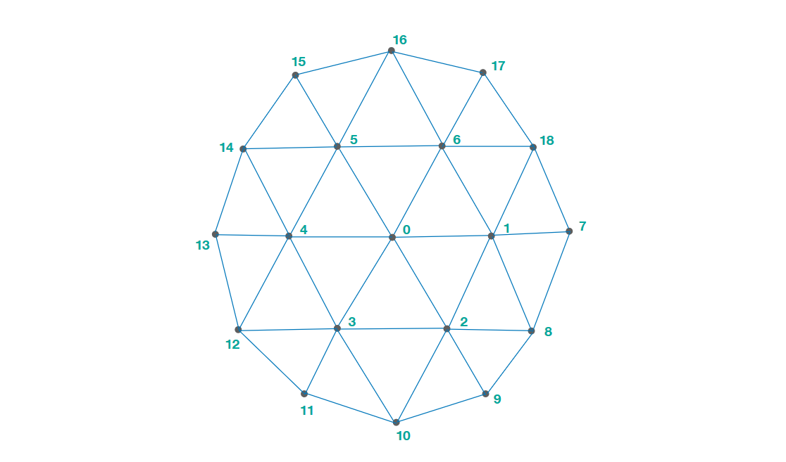
This mesh has:

  • 19 vertices (0 to 18)
  • 30 “half-edges” (edges shared by 2 triangles)
  • 12 “naked edges” (composing the outer circle)

Each vertex has a repulsive force and is connected to its neighbors by springs. It’s also important to note that inner vertices are of degree 6. For example, vertex n°5 have 6 incident edges, connecting it to its 6 adjacent neighbors (vertices n° 6, 0, 4, 14, 15 and 16)

Now, if I want to create ruffles (and as you’ve rightly suggested) I need to add many vertices around the outer circle. But this is precisely where all the problems begin.

“Adding vertices” means that I have to divide any triangle that is on the edge of the mesh (triangles that have a “naked edge”). But the question is what kind of division ?

I could split these triangles in half, over and over, like you seem to suggest.


(triangle 5-15-16 is split in half, then its inner triangles are split in half again and again)

But then that would mean that:

  • only the outer circle of the mesh is growing, not the mesh itself
  • the degree of the inner vertices is becoming way too high (here vertex n°5 is of degree 21 !!)

And I would end up with something looking like this:

From the different papers (about cellular growth simulation) that I’ve read it seems a good mesh (homogeneous and consistent) is composed of vertices that are, overall, of degree 7. Meaning that some vertices may be of degree 8 or 9, others of degree 5 or 6 but most have to be of degree 7.

In this case, given that I’m starting with inner vertices of degree 6, I’m allowed to connect them to 1 additional neighbor only. In other words, I can split in half a triangle (on the outer ring of the mesh) only once.

Of cource I can add some variety with a probabilistic function but the degree should not exceed 9 or 10.

But then another problem occurs: because of this limitation the growth is now constrained:


(newly added vertices in red, marking where former naked edges have been split. Inner vertices n°5, 6, 1, 2, 3 and 4 are all of degree 7: the growth is stopped.)

In order to prevent that behavior and unlock the growth process I tried to split the newly added edge in half to create a new inner vertex:

In the example above, the original triangle (5 -15 -16) is divided in 2 and the newly added edge (5 - 19) is split in half. The new inner vertex (20) is only of degree 4 and its adjacent triangles (15 - 20 - 19) / (19 - 20 - 16) can therefore be divided until it reaches degree 7.

Unfortunately, this workaround works poorly. Edges are growing but not uniformly and the overall shape is far from looking like the picture from Anders Hoff:

So the million-dollar question remains:

What kind of triangle division makes possible a uniform growth of the edges ?

1 Like

I think the approach I was suggesting was not actually subdivision – it was successive pressure applied to the perimeter of the rings of a regular hexagon lattice with triangular tiling. The triangles are all equilateral when at rest in 2D – when the grid “lies flat” it is equilateral triangle graph paper, ie the hexagonal lattice.

So, first build a hexagon out of triangles. Add a ring of regular triangles around it on the same grid, as in your example, and apply additional pressure to the perimeter edges only. Add another ring and repeat - perimeter only. Add another and repeat.

If you want to increase the resolution as you add rings – and note, this is in no way required to create ruffles – then on the next ring find the center of each equilateral triangle and subdivide it into three equilateral triangles (don’t split it into two right triangles and then split each, as you do in the figure above). Regardless of the resolution of a given row, apply pressure to the perimeter edges only to maximize ruffling. (Note I say “equilateral” only to describe the grid at rest in 2D, with no forces applied curling it into 3D. The point is that your subdivisions are fractal, no matter how many you add.)

This approach is untested – I’m just describing the process I had in mind based on the material you shared. I understand that you are looking for an algorithm that gives you degree 7-8, and I’m describing starting with degree 6–although randomly scattered subdivisions (or intermittent rings of subdivisions) would I believe push neighbors to degree 7 or 8. Still, this may be unrelated to the papers you are trying to replicate.

Keep in mind that there should be small forces and many rings. You aren’t liking these dramatically crumpled things, and they do have topology problems, but I suspect that you need lots of rings for a more subtle effect.

1 Like

Oh I see ! While I’m more interested in a morphogenetic approach (cells duplication / face subdivision) I got to say it’s a nice idea (thank you).

I tried to implement it, but ran into several issues:

  • the number of vertices around each circle is too small to create ruffles
  • when it does, the number of circles is usually way too large
  • applying “additional pressure” to the perimeter edges is not an easy task

Actually I’m wondering what did you mean exactly by “additional pressure”: decreasing the rest length of the spring on every perimeter edges while maintaining the repulsive force of its adjacent vertices ? Or the opposite ? (same rest length but higher repulsive forces as we get farther from the center)

For now I’m trying to get around these problems by creating a mesh where the number of vertices is increasing exponentially from one circle to another.

  • 1st circle: 1 * 1 * 6 = 6 vertices (hexagon)
  • 2nd circle: 2 * 2 * 6 = 24 vertices
  • 3rd circle: 3 * 3 * 6 = 54 vertices

I’m also applying a planar force to get smooth curves but this slows down the sketch as the calculation computes for each vertex the distances to its adjacent neighbors.

Proof of concept (Jeremy’s idea) using toxiclibs and hemesh (Python mode):

add_library('toxiclibs')
add_library('peasycam')
add_library('hemesh')
from toxi.physics3d.behaviors import AttractionBehavior3D
from toxi.physics3d import VerletPhysics3D, VerletParticle3D

repRadius = 15
repStrength = .4
sprStrength = .001

def setup():
    perspective(60 * DEG_TO_RAD, width/float(height), 2, 6000)
    translate(width>>1, height>>1)
    size(1000, 600, P3D)
    strokeWeight(.5)
    fill('#F1EF4D')
    smooth(8)
    
    global physics, vertices, mesh, render
    cam = PeasyCam(this, 180)
    render = WB_Render(this)
    physics = VerletPhysics3D()
    physics.setDrag(.4)
    
    N, radius = 9, 20
    vertices = [WB_Point(0,0)]
    
    # Displaying points (vertices) uniformly around the N circles
    for n in xrange(1, N+1):
        for i in xrange(6 * (n*n)):
            angle = radians(360) / (6 * (n*n))
            x = cos(angle*i) * radius * n
            y = sin(angle*i) * radius * n
            vertices.append(WB_Point(x, y))   
    
    # Creating a mesh based on the triangulation of these vertices
    triangulation = WB_Triangulate.triangulate2D(vertices)
    edges = triangulation.getEdges()
    mesh = HE_Mesh(HEC_FromTriangulation().setTriangulation(triangulation).setPoints(vertices))
    
    # Converting points (vertices) to VerletParticles and giving them a repulsive force
    for i, p in enumerate(vertices):
        v = VerletParticle3D(p.xf(), p.yf(), p.zf() + random(.001))
        physics.addParticle(v)
        physics.addBehavior(AttractionBehavior3D(v, repRadius, -repStrength))
        vertices[i] = v

    # Connecting vertices of the mesh (particles) with springs
    for i in xrange(0, len(edges), 2):
        v1 = vertices[edges[i]]
        v2 = vertices[edges[i+1]]
        spring = VerletSpring3D(v1, v2, v1.distanceTo(v2), sprStrength) 
        physics.addSpring(spring)

def draw():
    background('#E2ECF2')
    lights()
    
    # Updating physics engine
    physics.update()
    
    # Transfering the physics of the vertices to the mesh
    for i in xrange(len(vertices)):
        mesh.getVertex(i).set(WB_Point(vertices[i].x(), vertices[i].y(), vertices[i].z()))
    
    # Computing + applying planar force to vertices
    for i, p in enumerate(vertices):
        v = mesh.getVertex(i)
        center = Vec3D()
        for n in v.getVertexStar():
            center.addSelf(Vec3D(n.xf(), n.yf(), n.zf()))
        
        center.scaleSelf(1.0/len(v.getVertexStar()))
        dif = center.sub(p)
        p.addForce(dif)
        
    # Rendering
    render.drawFaces(mesh)


(rendering of a mesh composed of 16 circles and 8977 vertices)

I personaly find this output less interesting than the ones made from cellular growth, probably because of the missing fractal patterns (a pleat/fold born from another fold VS a continuous fold).

I might put my question about subdivision on stackoverflow. Not sure it will get answers but if it does, be sure I’ll update this thread.

2 Likes