How to fill circles in image (electric circuit)

Hi all

In this GitHub link

Javascript app to process a PCB image and output G-code suitable for laser engraver or similar machine. To reduce tool time

This is the PCB schematic image provided in the link

It’s ordinary PCB schematic the extra thing is that circles filled with Green

My question how to detect the circles (Holes)
Of this PCB image And filling with green color

actual-size-of-Single-sided-Copper-PCB-layout

My engraving machines

Thanks :pray::pray: in advance

1 Like

my idea would be to

  • make an internal copy of the image

  • go through the points of the copy of the image and check each one with a flood fill

  • when the flood fills less than 20 points (or whatever) we have whole and store the point.

  • when done, perform a flood fill for each of the found points in the original image

here is a flood fill


// phi.lho wrote: Toxi's flood fill code, updated to modern Java and Processing and to my taste... :-P
// Also generalized to work on any PImage
// http://processing.org/discourse/yabb2/YaBB.pl?num=1138719727


FloodFill1 myFloodFill ;
//
void setup() {
  size(900, 900);
  noFill();
  // strokeWeight(23);
}
//
void draw () {
  if (keyPressed) {
    // with key on keyboard pressed, you flood fill (that's used 2nd)
    if (mousePressed) {
      loadPixels();
      myFloodFill = new FloodFill1();
      myFloodFill.DoFill(mouseX, mouseY, color(255, 0, 0));
      updatePixels();
    }
  } else {
    // with key on keyboard NOT pressed, you draw (that's used 1st)
    if (mousePressed) {
      line(mouseX, mouseY, pmouseX, pmouseY);
    }
  }
}

// =====================================================================

// I create a class to share variables between the functions...
public class FloodFill1
{
  protected int iw; // Image width
  protected int ih; // Image height
  protected color[] imagePixels;
  protected color backColor; // Color found at given position
  protected color fillColor; // Color to apply

  // Stack is almost deprecated and slow (synchronized).
  // I would use Deque but that's Java 1.6, excluding current (mid-2009) Macs...
  protected ArrayList stack = new ArrayList();
  //
  public FloodFill1()
  {
    iw = width;
    ih = height;
    imagePixels = pixels; // Assume loadPixels have been done before
  }
  //
  public FloodFill1(PImage imageToProcess)
  {
    iw = imageToProcess.width;
    ih = imageToProcess.height;
    imagePixels = imageToProcess.pixels; // Assume loadPixels have been done before if sketch image
  }
  //
  public void DoFill(int startX, int startY, color fc)
  {
    // start filling
    fillColor = fc;
    backColor = imagePixels[startX + startY * iw];
    // don't run if fill color is the same as background one
    if (fillColor == backColor)
      return;

    stack.add(new PVector(startX, startY));
    while (stack.size () > 0)
    {
      PVector p = (PVector) stack.remove(stack.size() - 1);
      // Go left
      FillScanLine((int) p.x, (int) p.y, -1);
      // Go right
      FillScanLine((int) p.x + 1, (int) p.y, 1);
    }
  }
  //
  protected void FillScanLine(int x, int y, int dir)
  {
    // compute current index in pixel buffer array
    int idx = x + y * iw;
    boolean inColorRunAbove = false;
    boolean inColorRunBelow = false;

    // fill until boundary in current scanline...
    // checking neighbouring pixel rows
    while (x >= 0 && x < iw && imagePixels[idx] == backColor)
    {
      imagePixels[idx] = fillColor;
      if (y > 0) // Not on top line
      {
        if (imagePixels[idx - iw] == backColor)
        {
          if (!inColorRunAbove)
          {
            // The above pixel needs to be flooded too, we memorize the fact.
            // Only once per run of pixels of back color (hence the inColorRunAbove test)
            stack.add(new PVector(x, y-1));
            inColorRunAbove = true;
          }
        } else // End of color run (or none)
        {
          inColorRunAbove = false;
        }
      }
      if (y < ih - 1) // Not on bottom line
      {
        if (imagePixels[idx + iw] == backColor)
        {
          if (!inColorRunBelow)
          {
            // Idem with pixel below, remember to process there
            stack.add(new PVector(x, y + 1));
            inColorRunBelow = true;
          }
        } else // End of color run (or none)
        {
          inColorRunBelow = false;
        }
      }
      // Continue in given direction
      x += dir;
      idx += dir;
    } //
  } // func
} // class
// ----------------------------------------------------------

2 Likes

Very slow but might be easy to program

draw programs such as MS paint also have a fill function

1 Like

Thak you for your idea I am trying to understand the sketch

1 Like

result

I did it.

It’s another idea than mentioned.

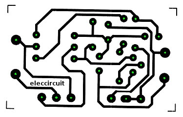
This Sketch just searches white points and

  • checks a circle around it. The entire circle must be black (surrounding the white hole).
  • It checks a 2nd circle around it. This must be mostly white (the white area around the black area).
  • When both circles are correct, we have found a hole.

The circles are critical in this project. For example you can change the radius. There are also two thresholds you can tinker with (for the counting of points of the 2 circles which is probably mostly due to rounding float to int…).

The correct points are stored (the holes).

You can delete points/rects that are wrong (they are in positions where in fact no hole is). These wrong rects are there because of the radius / threshold issues discussed above.

The green color is placed in the remaining holes.

The image is shown.

you can save with s.

Chrisir

// This Sketch can analyze an image of circuit where the holes for the pins are marked by black circles with a white hole.
// We fill these with green color.
// https://discourse.processing.org/t/how-to-fill-circles-in-image/42190/4

PImage img;
int iw;// its width

ArrayList<PVector> listOfHolePositions = new ArrayList();

int state=0;

// -----------------------------------------------------------------------------------------------------------
// Core functions

void setup() {
  size(900, 900);
  noFill();

  img=loadImage("c1.jpeg");

  iw = img.width;
}//func

void draw () {
  switch(state) {
  case 0:
    analyzeImage(); // search the holes
    break;

  case 1:
    showAndEditImage(); // edit the holes
    break;

  case 2:
    fillImage(); // fill the holes
    break;

  case 3:
    // image is ready
    showAndSaveImage();
    break;

  default:
    println("Error "+state);
    exit();
    break;
  }//switch
}//func

// -----------------------------------------------------------------------------------------------------------
// Inputs

void keyPressed() {
  //
  switch(state) {
  case 3:
    if (key=='s') {
      img.save("result.jpg");
      println("Saved.");
    }//if
  }//switch
}//func

// -----------------------------------------------------------------------------------------------------------
// Called from draw()

void analyzeImage() {
  image(img, 0, 0);

  box("Mouse "
    + mouseX + " , "
    + mouseY + ": color: "
    + get(mouseX, mouseY)
    + ":"
    + color(255)
    + "\nAny key to start (can take a minute!).");

  if (mousePressed) {
    analyzeOnePoint(mouseX, mouseY);
  }

  if (keyPressed) {
    print(">please wait...");
    img.loadPixels();
    searchImage();
    img.updatePixels();
    println("<");
    state=1;
  }
}//func

void showAndEditImage() {
  // when we have the points in the list, we can delete wrong points

  background(0);
  image(img, 0, 0);

  box("You can delete wrong rects by holding mouse and dragging over the top left corner. \nAny key to continue. ");

  // display
  for (PVector pv : listOfHolePositions) {
    fill(255, 0, 0);
    noStroke();
    rect(pv.x, pv.y, 8, 8);
  }

  // delete by mouse
  for (int i=listOfHolePositions.size()-1; i>=0; i--) {
    PVector pv=listOfHolePositions.get(i);
    if (mousePressed) {
      if (dist(mouseX, mouseY, pv.x, pv.y) < 4 )
        listOfHolePositions.remove(i);
    }
  }

  // go on
  if (keyPressed) {
    for (PVector pv : listOfHolePositions) {
      println(pv.x +","+pv.y);
    }
    state=2;
  }
} // func

void fillImage() {
  // when we have the points in the list,
  // we can flood fill them

  println("");
  print(">please wait...");
  img.loadPixels();
  for (PVector pv : listOfHolePositions) {
    fillMy (int(pv.x), int(pv.y),
      color( 0, 255, 0)); //Green
  }//for
  img.updatePixels();
  println("<");

  // go on
  state=3;
} // func

void showAndSaveImage() {
  background(0);
  image(img, 0, 0);
  box("DONE.\nHit 's' to save (overwriting)");
} // func

// ----------------------------------------------------------------------------------
// Tools I.

void fillMy(int x_, int y_,
  color col_) {
  // flood fill
  int dist = 5;
  for (int i1=-dist; i1<dist; i1++) {
    for (int i2=-dist; i2<dist; i2++) {
      // if white, fill it
      if (brightness(img.get(x_+i1, y_+i2))>22)
        img.set(x_+i1, y_+i2, col_);
    }
  }
} // func

// ----------------------------------------------------------------------------------
// Tools II.

void searchImage() {
  for (int startX=0; startX<img.width; startX++) {
    for (int startY=0; startY<img.height; startY++) {
      analyzeOnePoint(startX, startY);
    }//for
  }//for
}//func

void analyzeOnePoint(int startX, int startY) {
  // search a hole

  // wrong position?
  if (! (startX<iw&&startY<img.height)) {
    return;
  }

  // wrong color?
  color backColor = img.pixels[startX + startY * iw];
  if (backColor!=color(255)) {
    return;//skip
  }

  // it's white from now on

  // 1. count black points within inner circle.
  int countBlack=0;
  for (int angle=0; angle<360; angle++) {
    float xC=cos(radians(angle))*6+startX;
    float yC=sin(radians(angle))*6+startY;

    // stroke(255, 0, 0);
    // point(xC, yC);

    if (xC>=0&&yC>=0) {
      if (xC<iw&&yC<img.height) {
        if (img.pixels[int(xC) + int(yC) * iw] == color (0) ) {
          countBlack++;
        }
      }
    }
  }

  // 2. count WHITE points within outer circle.
  int countWhite=0;
  for (int angle=0; angle<360; angle++) {
    float xC=cos(radians(angle))*13+startX;
    float yC=sin(radians(angle))*13+startY;

    //stroke(255, 0, 0);
    //point(xC, yC);

    if (xC>=0&&yC>=0) {
      if (xC<iw&&yC<img.height) {
        if (img.pixels[int(xC) + int(yC) * iw] == color (255)) {
          countWhite++;
        }
      }
    }
  }

  fill(0);
  text(countWhite+":"+countBlack,
    width-100+66, 200);

  //stroke(0, 255, 0);
  //point(startX, startY);
  noStroke();

  // When the number of counts is correct, we have a hole
  // if (countBlack>210 && countWhite>170) {
  if (countBlack>180 && countWhite>160) {
    //match
    listOfHolePositions.add(new PVector(startX, startY)) ;
  }//if
}

// ----------------------------------------------------------
// Minor Tools

void box(String text_) {
  // box with text

  // box
  fill( #FAF028 );//Yellow
  noStroke();
  rect(width-180, 3,
    170, 300);

  // frame
  float dist1=4;
  noFill();
  stroke(0);
  rect(width-180+dist1, 3+dist1,
    170-2*dist1, 300-2*dist1);

  // state
  fill(0);
  text ("state "+state, width-160, 22 );

  // text
  text(text_,
    width-170, 100,
    150, 900);
}//func
//

2 Likes

@Chrisir

Thank you so much :pray::pray::pray:

1 Like

Normal Image recognition is done with library like openCV

There are also means to convert the image in an image where only single lines and circles are used

Then the analyzing is easier since we don’t have to work with different thicknesses of the lines and circles

Bit like here Straight Skeleton - or how to draw a center line in a polygon or shape?

1 Like

@chrisir neat idea to use the flood fill to find the holes. I love algorithms so I was interested in seeing if there was another way to do it and came up with this potential solution.

The video shows the sketch in action and as you might notice processes the image very quickly, just 5ms on my machine. It use the G4P library for the slider but all the work is done in the processImage method so would be easy in incorporate into an existing sketch. The only user defined variable is res which determines the maximum size of any hole.

import g4p_controls.*;

PImage img, pimg;
int res = 3; // keep this as small as possible to just find the holes

public void setup() {
  size(800, 320, JAVA2D);
  // Constrain 'res' to permitted slider values
  res = constrain(res, 1, 40);
  // create G4P controls
  createGUI(); 
  // Load and process PCB image
  img = loadImage("pcb_01.jpeg");
  pimg = processImage(img, res);
}

PImage processImage(PImage img, int r) {
  PGraphics pg;
  int w = img.width;
  int h = img.height;
  // Prepare buffer image
  pg = createGraphics(w, h);
  pg.beginDraw();
  pg.image(img, 0, 0);
  pg.endDraw();
  // Search for sequences [black] [whites] [black] where the maximum number
  // of enclosed whites  is <= r
  // Create array to store sequences of white pixels
  int[][] hp = new int[w][h];
  pg.loadPixels();
  int[] a = pg.pixels;
  // Scan PCB image horizontally
  for (int y = 0; y < h; y++) {
    int start = -1, count = 0;
    for (int x = 0; x < w; x++) {
      boolean isWhite = (a[y * w + x]  & 255) > 128; // false = black : true = white
      if (isWhite) { // White
        if (start < 0) start = x;
        count++;
      } else { // Black
        if (start >= 0 && count <= r) {
          for (int px = start; px < start + count; px++)
            hp[px][y]++;
        }
        start = -1;
        count = 0;
      }
    }
  }
  // Scan PCB image vertically
  for (int x = 0; x < w; x++) {
    int start = -1, count = 0;
    for (int y = 0; y < h; y++) {
      boolean isWhite = (a[y * w + x]  & 255) > 128; // false = black : true = white
      if (isWhite) { // White
        if (start < 0) start = y;
        count++;
      } else { // Black
        if (start >= 0 && count <= r)
          for (int py = start; py < start + count; py++)
            hp[x][py]++;
        start = -1;
        count = 0;
      }
    }
  }
  // Colour in pixels found in both scans
  for (int y = 0; y < h; y++)
    for (int x = 0; x < w; x++)
      if (hp[x][y] > 1)
        pg.pixels[y * w + x] = 0xFF66FF66;
  pg.updatePixels();
  return pg;
}

void draw() {
  background(200, 200, 255);
  image(img, 0, 0);
  image(pimg, 400, 0);
}


// All the following code is related to G4P
public void changeResolution(GCustomSlider source, GEvent event) {
  pimg = processImage(img, source.getValueI());
}

public void createGUI(){
  G4P.messagesEnabled(false);
  G4P.setGlobalColorScheme(GCScheme.BLUE_SCHEME);
  G4P.setMouseOverEnabled(false);
  G4P.setDisplayFont("Arial", G4P.PLAIN, 18);
  G4P.setSliderFont("Arial", G4P.PLAIN, 12);
  surface.setTitle("Sketch Window");
  lblResolution = new GLabel(this, 20, 260, 110, 60);
  lblResolution.setTextAlign(GAlign.CENTER, GAlign.MIDDLE);
  lblResolution.setText("Resolution");
  lblResolution.setOpaque(true);
  sdrResolution = new GCustomSlider(this, 130, 260, 650, 60, "blue18px");
  sdrResolution.setShowValue(true);
  sdrResolution.setShowLimits(true);
  sdrResolution.setLimits(res, 1, 40);
  sdrResolution.setNbrTicks(40);
  sdrResolution.setStickToTicks(true);
  sdrResolution.setShowTicks(true);
  sdrResolution.setNumberFormat(G4P.INTEGER, 0);
  sdrResolution.setOpaque(true);
  sdrResolution.addEventHandler(this, "changeResolution");
}

GLabel lblResolution; 
GCustomSlider sdrResolution; 
3 Likes

Very creative idea so great

1 Like

Hi jafal.

It makes me happy to know that somebody is trying to use my jsVoronoiPCB project. I can see when people clone the repo, but this is the first time I have seen proof that someone is really trying to make it work, and even inspecting the code! I hope you have fun and make some cool things!

Cheers,
Craig

2 Likes

Hi and welcome to our nice community

Thank you for your idea it is saving time and laser life hours I have test your image using windows 7 chrome browser the result is so great

But the PCB image I provided not that much how to enhance it and get same yours ?

Is there issue with resolution or image size??

Thanks in advance

1 Like

Hi. The artwork you provided in this thread is small. I upscaled it by 400% and got a reasonable result, except the text was obscured.

The best results are from a higher resolution.

Also, the g-code output will be smaller when the traces run perfectly horizonal, vertical, and 45-degree diagonal, (perfectly square within the frame) because my project only knows how to interpolate lines like that. (That shouldn’t be a big problem, there will just be more output coordinates in the output.)

Lastly, I don’t know how many dots-per-inch or dots-per-cm this image is, but that is important input for the conversion.

Hi Sir

Thank you now every thing is clear and understood … It’s very creative project