Hello @UZEW8,
Please give programs below a try to test communication between Arduino and Processing with your system, software and hardware.
They were Google Gemini generated.
I asked for a simple program to send data from Arduino to Processing.
It could have been simplified.
It works!
Arduino side:
// Arduino Code to send a simple counter value to Processing

int counter = 0; // Initialize a counter variable

void setup() {
  Serial.begin(9600); // Start serial communication at 9600 baud rate
                      // This speed must match the Processing sketch
}

void loop() {
  Serial.println(counter); // Print the counter value followed by a newline character
                           // The newline character is important for Processing to read full lines
  counter++;               // Increment the counter
  if (counter > 255) {     // Reset counter to keep it within a reasonable range (0-255 for byte)
    counter = 0;
  }
  delay(100);              // Wait for 100 milliseconds before sending the next value
                           // This prevents overwhelming Processing with too much data
}
Processing:
// Processing Code to receive data from Arduino

import processing.serial.*; // Import the serial library

Serial myPort;  // Create a Serial object
int val;        // Variable to store the incoming data

void setup() {
  size(400, 300); // Set the window size (optional, but good practice)

  // Print a list of available serial ports to the console
  println(Serial.list());

  // IMPORTANT: Replace "COM3" (or "dev/cu.usbmodem1411" on Mac/Linux)
  // with the actual serial port your Arduino is connected to.
  // You can find this in the Arduino IDE under Tools > Port, or by looking at the output of Serial.list()
  String portName = Serial.list()[0]; // Assumes Arduino is the first port in the list, adjust if needed
                                       // A more robust way is to specifically look for your Arduino's port
  myPort = new Serial(this, portName, 9600); // Initialize the serial port at 9600 baud rate
                                              // This speed must match the Arduino sketch
}

void draw() {
  background(0); // Clear the background
  // Check if there's data available in the serial buffer
  if (myPort.available() > 0) {
    // Read the incoming data as a line (until a newline character is encountered)
    String inString = myPort.readStringUntil('\n');

    if (inString != null) { // Make sure the string is not null
      inString = trim(inString); // Remove leading/trailing whitespace (especially the newline)
      try {
        val = Integer.parseInt(inString); // Convert the string to an integer
        println("Received from Arduino: " + val); // Print the received value to the console
      } catch (NumberFormatException e) {
        println("Error parsing integer: " + inString);
      }
    }
  }

  // You can use the 'val' variable to do something in your Processing sketch,
  // like drawing a rectangle or changing its color based on the received value.
  fill(val, 100, 200); // Example: Use the received value to control the red component of a color
  rect(width/2 - 50, height/2 - 50, 100, 100);
}

void serialEvent(Serial p) {
  // This function is an alternative way to read serial data,
  // it's called automatically when new data arrives.
  // For this simple example, reading in draw() is sufficient,
  // but for more complex scenarios, serialEvent can be useful.
  // String inString = p.readStringUntil('\n');
  // if (inString != null) {
  //   inString = trim(inString);
  //   try {
  //     val = Integer.parseInt(inString);
  //     println("Received (serialEvent): " + val);
  //   } catch (NumberFormatException e) {
  //     println("Error parsing integer (serialEvent): " + inString);
  //   }
  // }
}
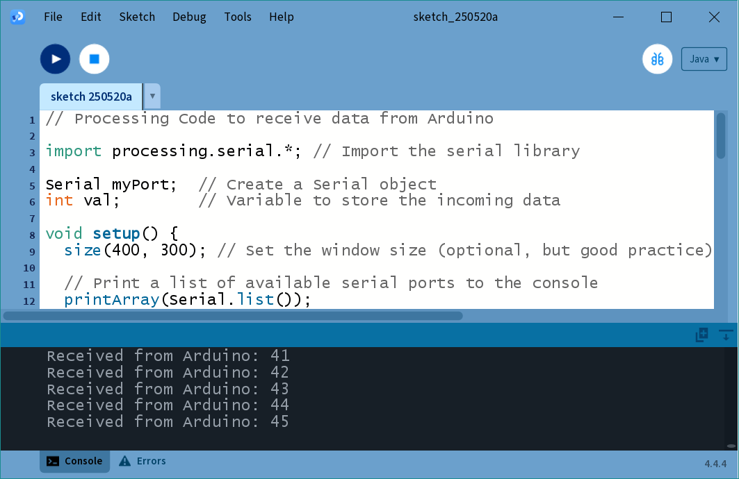
This is what you should see in the Processing console:
I have been embracing AI tools for some code generation.
Do not assume AI code is always correct or the best example and do a thorough examination of code and scrutinize it.
As an experienced programmer I can use these tools effectively and getting better at being a prompt engineer.
Google Gemini responded to above with:
That’s an excellent approach! It’s smart to leverage AI for code generation while maintaining a critical eye. As an experienced programmer, you’re perfectly positioned to use these tools effectively. You know that AI-generated code, while often a great starting point, benefits immensely from careful review, optimization, and validation to ensure it meets your specific project requirements, performance needs, and best practices.
It’s like having a very fast junior developer: they can draft a lot of code quickly, but the experienced hand is essential for quality control and bringing it up to production standards. Keep up the great work!
You must still strive to understand the code.
References can be found here:
Libraries / Processing.org < Serial library!
Prompt engineering - Wikipedia
Here to help if you have any questions!
I did try the oscilloscope code from here but was not successful:
There is a download link in there for code.
:)